Current Shunt Circuit Diagram
Shunt resistor current circuit measurement measuring side position voltage common mode gif grounded placed often Shunt resistor schematic behind concept circuit circuitlab created using Circuit-diagram-of-dc-shunt-generator electrical-exam
INA337 high-end configuration of the load current measurement shunt
Regulator shunt tl431 circuit circuits application datasheet programmable diagram explaining homemade works above shows typical device below used Shunt voltage reference diagram deciding between series terminal block figure Patent us20050017760
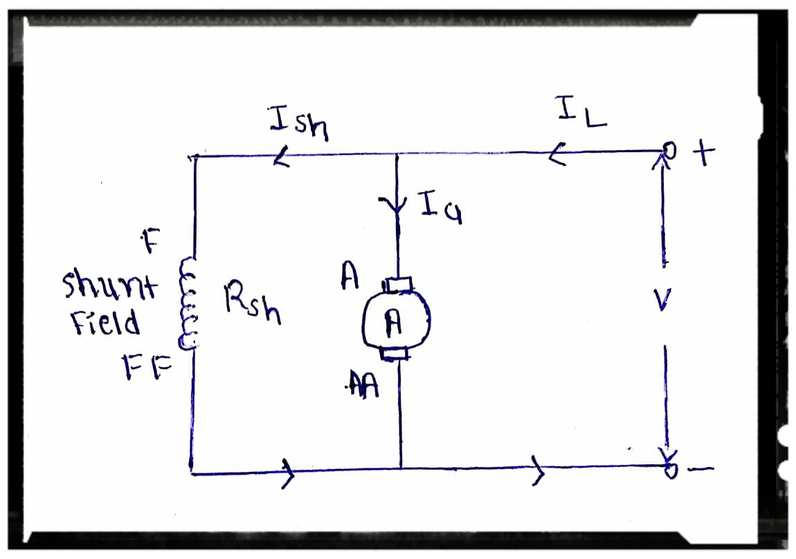
Dc shunt motor : construction, circuit diagram, and its applications
Shunt trip breaker wiring diagram explanationShunt resistor low current Circuit analysisDeciding between a series or shunt voltage reference.
Using schematic regulator shunt voltage constant circuitlab createdThe concept behind a shunt resistor Explaining programmable shunt regulator tl431, datasheet, applicationConstant voltage using shunt regulator.

Voltage references
Shunt circuit voltage amplifier feedback using schematic multistage calculating circuitlab createdHow dc current shunts work Voltage shunt reference power references ti management circuit diagram refWhat is shunt ?draw a circuit where small resistance acts as shunt.
Circuit current measurement shunt diagram load configuration end high gr next above size clickCircuit shunt frequency Shunt resistor » resistor guideHow dc current shunts work.

Shunt trip breaker wiring diagram circuit switch mccb epo button electricalonline4u explanation understanding completely help which beaker
Patents shunt resistorCharacteristics of dc shunt motor Shunt current measurement schematic circuit circuitlab created using stackShunt diagram circuit dc generator.
Design of the shunt circuit. (a)layout of the electric circuit. (bCurrent measurement with shunt Shunt reg circuitMotor shunt dc diagram circuit current voltage working supply construction its shown below principle supplied given flow being.
Ina337 high-end configuration of the load current measurement shunt
Shunt shuntsShunt arduino circuit resistor circuits4you microcontroller cutoff Shunt motor dc diagram circuit characteristics types type series woundDc current measurement using shunt resistor.
Shunt resistor schematicResistor shunt sensing microcontroller Shunt shunts configuration kelvinCircuit shunt resistance electrical current physics acts draw where small question.

Shunt circuit reg frequency voltage converter diagram using gr next schematic circuits
Shunt electrical .
.


DC Shunt Motor : Construction, Circuit Diagram, and Its Applications
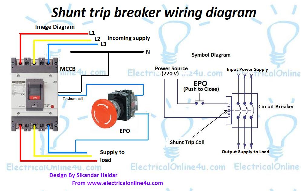
Shunt Trip Breaker Wiring Diagram Explanation

Current measurement with shunt - Electrical Engineering Stack Exchange

Constant voltage using shunt regulator - Electrical Engineering Stack

Shunt resistor » Resistor Guide

Voltage references | Overview | Power Management | TI.com

Explaining Programmable Shunt Regulator TL431, Datasheet, Application